Arduino Stopwatch timer for Science expo project
Primary tabs
My son Liam is doing a Science expo project. It's sort of like a science fair, but in second grade they don't do judging. It's just a demonstration, and he'll get a participation ribbon. I don't really care about that, I just want him to start learning the scientific method.
He came up with a great idea. He wanted to put an ice cube in a frying pan and watch it dance around. I tried to work with him on that idea, but I realized two problems:
- There wasn't really a hypothesis he wanted to test. It was really just to watch something cool. I certainly don't object to that. Wanting to see something cool is at the heart of science. Plus, a demonstration of a concept is a valid topic for the expo, (not quite sure what the exact concept would be here) . . . BUT
- Hot frying pan in an auditorium filled with 7 year olds. Not going to happen.
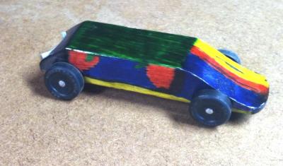 I kind of steared him to do something related to our last project, which was the pinewood derby car he and I built for the Cub Scouts.
I suggested using his car, and putting more or less weight on it, and then measuring how long it takes to go down a ramp. It was something we wondered about as we were building the car anyway. Conventional wisdom in the context of the race is to make the car as heavy as possible (within the rules), which works out to as close to 5 ounces as possible without going over. But if we do it for this, we can measure it anywhere from about 3 oz up to several pounds, and see how the speed of a free-wheeling vehicle down an incline is impacted by changing weight. He seemed to like the idea.
So I'm balancing two things here: teaching my son about science, and giving myself an opportunity to build something out of wood (the ramp) and with an Arduino (the timer). I've got until early March to finish this. The rule of the design was to use things we already had on hand, so I designed it around an 8' long track built with some scrap lumber I have in the shop, and to use the Arduino Uno I've been playing with to handle the timing. Believe it or not, I've actually already built the ramp.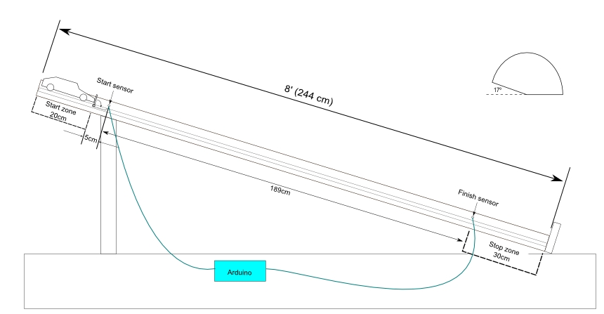
The concept is to put a basket on top of the car and run it down the ramp, timing how long it takes to go between two sensors. We will place additional weights in the basket to determine the overall weight of the car. I wanted to use a basket so that the airflow of the car doesn't change between measurements. The car traveling down the track will break a light beam to start and stop the timer. The top sensor will start a milli-second timer, and the sensor at the bottom of the track will stop the timer. And Liam will write down the car's weight and time in his handy-dandy science notebook. I'm hoping he thinks it's fun. We shall see.
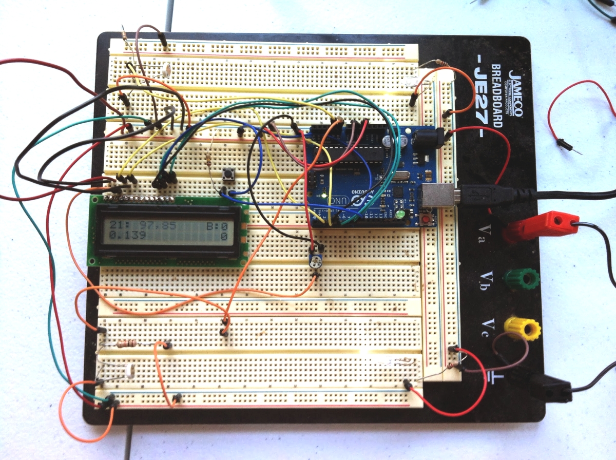
As for the Arduino timer, I'm about 75% done with the prototype. I'm basing it on the millis() procedure for timing using the Arduino's crystal oscillator, starting from Paul Badger's Stopwatch sketch from the Arduino Playground.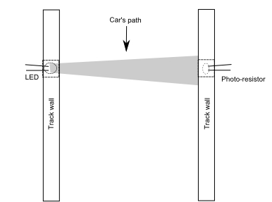 The photo sensors are, of course, the tricky part. I'm not using laser diodes, since I didn't have any on hand. A couple of fairly bright white LEDs will have to do. From my tests, the photo-resistors will work, as long as the ambient light reaching them in the side walls of the track is not too bright. I've got a prototype working that has the two photo resisters registering when the light 'beam' from two LEDs are broken, and it has a push button to start and stop the timer. My next step is to hook the timer up to the light sensors, so to speak. It's all in the sketch. I'll post my prototype sketch as soon as I get the sensors driving the timer.
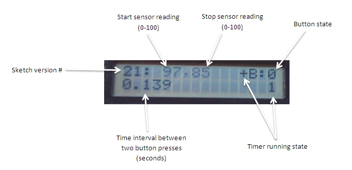 I'm numbering my sketches as I repeatedly update them. Here, this is the way the sketch stood last night: Click on the photo to see some details about what I'm reporting on the screen. The pot in the image is just the one used to set the contrast of the LCD. Unfortunately, I only have a basic LCD. It has no backlight. Maybe I'll pick up a better one before I build the final version.
For the track tests, I'm going to put the LCD and Arduino in a project box and run it off of a 9V battery. I've got a little 350mA 5V wall wart running the LED timing lights.
| Attachment | Size |
|---|---|
| 20.3 KB |