Timer Prototype Finished

  • Posted on: 19 February 2014
  • By: Jay Oyster

February 19, 2014 - OK, I first posted on this project a couple of days ago. I've got a short window to get this working. Liam's science expo is on March 7th, and I need to complete the track (with attached timer) in time so Liam and I can run a set of experiments. So late last night, I managed to finish the prototype of the Arduino timer I plan to mount to the side of the test track. It's all breadboarded now, and I'll probably just use the prototype to run the timing for Liam. After we get some results on paper, I'll worry about turning this into a sturdy version permanently attached to the side of the track.
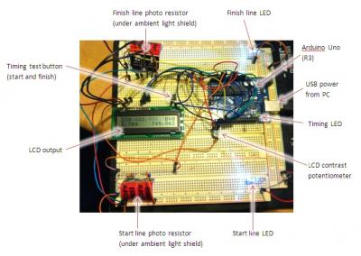
Layout of the prototypeThe hardware work was basically done last week. I just needed to figure out the update to the sketch to figure out how to trigger the timing code using the inputs from the two photo-resistor sensors.  The picture here shows the prototype board, as it's currently working. Click the image to enlarge it.

I'm using the following inputs and outputs on the Arduino:

LCD I/O:
 RS:  Pin 2
 EN: Pin 3
 D4: Pin 4
 D5: Pin 5
 D6: Pin 6
 D7: Pin 7

Other I/O:
 Start/stop button input: digital pin 8
 Timing indicator LED: digital pin 13
 Start line sensor input: analog pin 0
 Finish line sensor input: analog pin 1

I made a short video last night showing how it functions in operation. (This also happens to be my first video uploaded to Youtube. . . hard to believe. What can I say, I'm shy. ;-) )

The power needs of the sensors was a concern during the process. Running the LCD, both sensor inputs and both source LEDs off of the Arduino power wasn't going to work, with a limit of around 50mA for all outputs (realistically, it seemed to tank at about 100mA). So I'm running the two 'lightbeam' LEDs off of an external 350mA, 5V wall wart I had laying around.  When I convert this to a boxed project, I'll probably run everything off of it.

The other key parameter, as it operates now, is the way I detected the light beam being broken. Since the photoresistors output is highly dependent on the ambient light in the room, I decided to go full range on the analog inputs (so, a range from 0-1023) and then opted to calculate the detection range each time the board is powered up or reset. But what light drop would cause the detection. After playing with the system in a dark room and then in a room in full daylight from nearby windows, the best option was a drop of about 8%. This way the system automatically adjusts to ambient light conditions, at least when I restart the board, and it successfully detects the beam being broken whether the room is in full light or complete darkness. In sketch #30, I added these calculated threshold sensor values to the right end of the second row on the LCD screen. (I removed the secondary indicator of the 'blinking' variable that had been displayed in the bottom right corner of the display, since the timing "+" sign on the first row took care of that feedback.) Take a look at the video; you should be able to see what I mean.

This is the code I used in the prototype, which I called 'Sketch 30'

//Twin Lightbeam Timer with LCD Output, by Jay Oyster
//LCD Library by David Mellis, Limor Fried, and Tom Igoe
//Initial LCD code based on work by Jeremy Blum
//Timer and Blink routines based on the StopWatch sketch by Paul Badger
//Uses the onboard crystal clock and the millis() routine to 1) keep track of the time when the beam is started and stopped
//  and 2) blink the LED at regular intervals to show when the timer is running

/*
 * RS: Pin 2
 * EN: Pin 3
 * D4: Pin 4
 * D5: Pin 5
 * D6: Pin 6
 * D7: Pin 7
*/

//Include the LCD Library
#include <LiquidCrystal.h>

//Constants for button pin input, LED counting pin output, light sensor threshold value, and the sketch build number
#define sketchNumber 30             // Version of the sketch software, displayed in upper left corner of LCD
#define buttonPin 8                 // button on pin 8
#define ledPin  13                  // LED connected to digital pin 13
#define thresholdPercent 8          // The percentage points below 100% of initial light level to trigger the counter start and stop

//Initialize an LCD object
LiquidCrystal lcd(2,3,4,5,6,7);

//Variables for the read and display of photoresistor values, to track the state of a button input and and LED output, and to store timing values
int lightPin1 = 0;                  // Define a pin for start gun Photo resistor
int lightLevel1 = 0;                // Place to store light level value from first photo resistor
int threshold1 = 0;                 // Calculated level to trigger counter start
int lightPin2 = 1;                  // Define a pin for the stop gun photo resistor
int lightLevel2 = 0;                // Place to store light level value from second photo resistor
int threshold2 = 0;                 // Calculated level to trigger counter stop
int lastLightLevel1 = 0;            // Used to store previous lightlevel value to debounce the start trigger
int lastLightLevel2 = 0;            // Used to store previous lightlevel value to debounce the stop trigger
int value = LOW;                    // previous value of the LED
int buttonState = false;            // variable to store button state
int lastButtonState = false;        // variable to store last button state
int blinking = false;               // condition for blinking - timer is timing
long interval = 100;                // blink interval - change to suit
long previousMillis = 0;            // variable to store last time LED was updated
long startTime ;                    // start time for stop watch
long elapsedTime ;                  // elapsed time for stop watch
int fractional;                     // variable used to store fractional part of time

void setup()
{
  //initialize pin i/o states
  pinMode(ledPin, OUTPUT);         // sets the digital pin as output
  pinMode(buttonPin, INPUT);       // not really necessary, pins default to INPUT anyway
 
  //Begin the LCD interface
  lcd.begin(16,2);

  //Print my name
  lcd.setCursor(0,0);
  lcd.print("S");
  lcd.print(sketchNumber);

 //Initialize start button
 pinMode(buttonPin, INPUT);       // not really necessary, pins default to INPUT anyway
 digitalWrite(buttonPin, LOW);   // turn on pullup resistors. Wire button so that press shorts pin to ground.

 //Calculate the optical sensor trigger levels for the counter
 lightLevel1 = analogRead(lightPin1);
 lightLevel2 = analogRead(lightPin2);
 threshold1 = (lightLevel1*((100-thresholdPercent)/100.0));
 threshold2 = (lightLevel2*((100-thresholdPercent)/100.0));
 
 //Print out the threshold values on row 2 of the LCD
 lcd.setCursor(9,1);
 lcd.print(threshold1);
 lcd.print(",");
 lcd.print(threshold2);
}

void loop()
{
 //Move the cursor
 lcd.setCursor(0,1);

 //Clear the line
 //lcd.print("        ");
 
 lcd.setCursor(13,0);
 lcd.print("B:");
 lcd.print(digitalRead(buttonPin));
 
 //Send the value measured on Analog pin 0 to the serial port & print to the LCD screen
 lightLevel1 = analogRead(lightPin1);
 lightLevel2 = analogRead(lightPin2);
 //lightLevel1 = constrain(lightLevel1,800,950);
 //lightLevel1 = map(lightLevel1,400,900,0,100);
 //lightLevel2 = map(lightLevel2,800,1000,0,100);
 //Serial.print(lightLevel1); //Write the value of the photoresistor to the serial monitor
 //Serial.print(", ");
 //Serial.println(lightLevel2);
 lcd.setCursor(4,0);
 lcd.print("        ");
 lcd.setCursor(4,0);
 lcd.print(lightLevel1);
 lcd.print(",");
 lcd.print(lightLevel2);
 
 //delay(50);
 
 //pasted in timer and LED blinking routines from Stopwatch sketch
 // check for button press
   buttonState = digitalRead(buttonPin);                   // read the button state and store

   if (((buttonState == LOW && lastButtonState == HIGH) || (lightLevel1 <= threshold1))  &&  blinking == false){     // check for a high to low transition
      // if true then found a new button press while clock is not running - start the clock

      startTime = millis();                                   // store the start time
      blinking = true;                                     // turn on blinking while timing
      delay(5);                                               // short delay to debounce switch
      lastButtonState = buttonState;                          // store buttonState in lastButtonState, to compare next time
      lastLightLevel1 = lightLevel1;                          // store lightlevel in lastLightLevel, to compare next time
      lastLightLevel2 = lightLevel2;

      //Turn on timing indicator
      lcd.setCursor(12,0);
      lcd.print("+");
   }

   else if (((buttonState == LOW && lastButtonState == HIGH) || (lightLevel2 <= threshold2)) && blinking == true){     // check for a high to low transition
      // if true then found a new button press while clock is running - stop the clock and report

        elapsedTime =   millis() - startTime;              // store elapsed time
        blinking = false;                                  // turn off blinking, all done timing
        lastButtonState = buttonState;                     // store buttonState in lastButtonState, to compare next time
       
        //Turn off timing indicator
        lcd.setCursor(12,0);
        lcd.print(" ");

       //Clear previous time
       lcd.setCursor(0,1);
       lcd.print("        ");
      
     
       // routine to report elapsed time
        Serial.print( (int)(elapsedTime / 1000L));         // divide by 1000 to convert to seconds - then cast to an int to print
        Serial.print(".");                             // print decimal point
        lcd.setCursor(0,1);
        lcd.print((int)(elapsedTime / 1000L));
        lcd.print(".");

        // use modulo operator to get fractional part of time
       fractional = (int)(elapsedTime % 1000L);

       // pad in leading zeros - wouldn't it be nice if
       // Arduino language had a flag for this? :)
       if (fractional == 0)
          lcd.print("000");      // add three zero's
       else if (fractional < 10)    // if fractional < 10 the 0 is ignored giving a wrong time, so add the zeros
          lcd.print("00");       // add two zeros
       else if (fractional < 100)
          lcd.print("0");        // add one zero

       lcd.print(fractional);  // print fractional part of time

   }

   else{
      lastButtonState = buttonState;                         // store buttonState in lastButtonState, to compare next time
     
   }

   // blink routine - blink the LED while timing
   // check to see if it's time to blink the LED; that is, the difference
   // between the current time and last time we blinked the LED is larger than
   // the interval at which we want to blink the LED.

   if ( (millis() - previousMillis > interval) ) {

      if (blinking == true){
         previousMillis = millis();                         // remember the last time we blinked the LED
        
         // if the LED is off turn it on and vice-versa.
         if (value == LOW)
            value = HIGH;
         else
            value = LOW;
         digitalWrite(ledPin, value);
      }
      else{
         digitalWrite(ledPin, LOW);                         // turn off LED when not blinking
      }
    
     // Print out the value of the blinking variable in the last character of the 2nd row on the LCD
     // lcd.setCursor(15,1);
     // lcd.print(blinking);
   }

 
}


Timer with LCD and two LED/photoresistor pairs to detect start and stop times, with Sketch#30 running
Electronics and Software Development
Woodworking