Lighthouse update: Adding Screen and Coding
Primary tabs
 OK, to reiterate where we are in the build of this Smart Weather Lighthouse build, up to this point I had configured the sound files and sound boards to play when triggered, and powered on and loaded Circuitpython on the Metro MX board. Up next, I'll go through how I got the 4.7" touchscreen attached and operating. And then talk about getting data back to the Metro board using the OpenWeather API, and finally, attaching the clock.
- Configuring the sound boards, speakers and audio sample files - DONE
- Setting up the MX board with Circuitpython and activating wifi and basic code - DONE
- Attaching the touchscreen driver board and touchscreen to the Metro MX board - This update
- Initializing the Openweathermap API calls for local weather data - This update
- Attaching the realtime clock board to the Metro MX - This update
- Building the basic touchscreen user interface
- Wiring the lighthouse lights and motor to the Metro MX board
- Triggering sound effects with the Metro MX Board
- Building the wooden lighthouse base Installing the electronics into the base
Connecting the Touchscreen Driver Board and Touchscreen
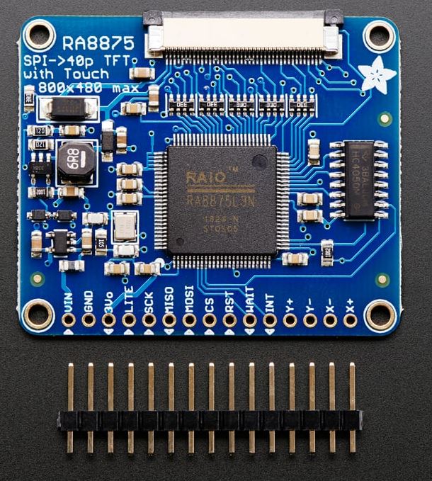
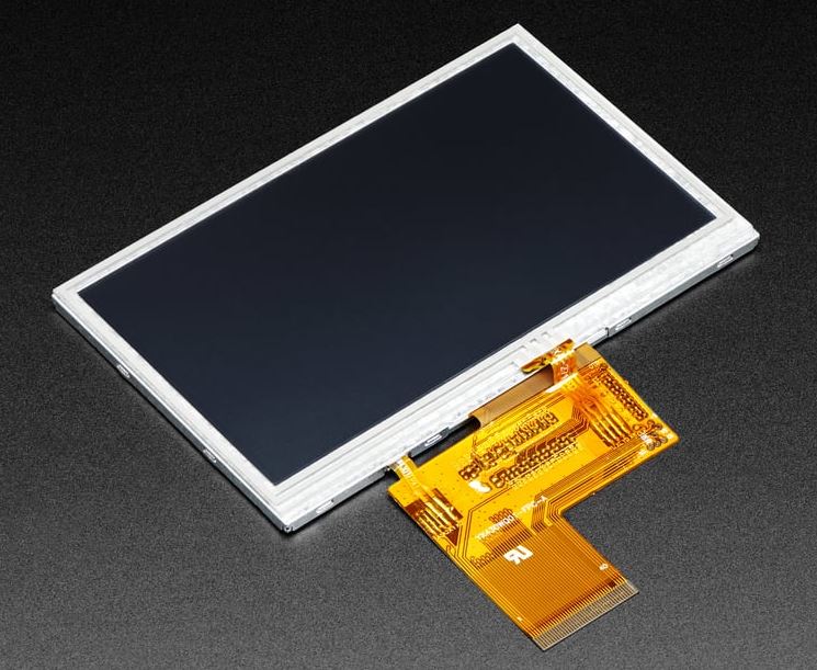 The 4.3" 40-pin TFT Display display I ordered has 480 by 270 pixels, a backlight, and a touchscreen overly, but no onboard memory or display controller. So I needed a chip to drive this thing. Adafruit has a board mounted RA8875 TFT driver chip mounted on a board with the necessary 40 pin FPC port to receive the ribbon cable from the display.
So the RA8875 board comes with the header, but again I needed to attach it. Using a breadboard, I first sized the header to the correct number of pins. (These headers snap off at whatever length you need.) I pushed the header into the breadboard, and placed the RA8875 on top of the pins, using the breadboard mount as a convenient holder while I soldered the header in place. This project certainly allowed me to refresh and refine my fine electronics soldering skills. I find this kind of soldering both medatitive and mindful. It reminds me of final planing of board on a fine woodworking project. Or softening the edges of a board using a block plane. These are the things . . . little, detailed, creative, and functional tasks . . . that make me love this sort of work.
 So with the header in place, and the Metro board powered off and disconnected from the USB cable to the PC, I wired the display driver board for 5 VDC and ground coming from the Metro board. We're using SPI to control the display driver from the microprocessor. So next I connected these lines between the Metro and the RA8875, using patch wires:
 - MISO to MISO (RA8875 to Metro comms)
- MOSI to MOSI (Metro to RA8875 comms)
- SCK to SCK (clock)
- Digital pin 9 to CS (chip select)
- Digital pin 10 to RST (reset)
- Digital pin 11 to INT (touchscreen interrupt signal)
Pins 9, 10, and 11 are the default pins used by the sample CircuitPython code for the RA8875, and I opted to just keep those pin outs. Adafruit has provided a very helpful RA8875 Circuitpython library that quickly gets the board up and talking to the Metro and also provides methods for graphics primitives for the display. That library is available on github. And there's a great tutorial about getting this board working here: https://learn.adafruit.com/ra8875-touch-display-driver-board/circuitpython
import time import busio import digitalio import board from adafruit_ra8875 import ra8875 from adafruit_ra8875.ra8875 import color565cs_pin = digitalio.DigitalInOut(board.D9) rst_pin = digitalio.DigitalInOut(board.D10) int_pin = digitalio.DigitalInOut(board.D11) BAUDRATE = 6000000 spi = busio.SPI(clock=board.SCK, MOSI=board.MOSI, MISO=board.MISO) display = ra8875.RA8875(spi, cs=cs_pin, rst=rst_pin, baudrate=BAUDRATE)
display.init()Anyway, (I'm taking too long describing this) . . . the display was up and running, and I started using the commands in the adafruit_RA8875 library to draw to the screen. These were the most useful commands. Pretty much everything I put on the screen throughout the rest of this was done with these simple calls:
RED = color565(255, 0, 0)
display.fill(RED)
display.fill_rect(10, 10, 400, 200, RED)
display.rect(10, 10, 400, 200, RED)
display.line(10, 10, 200, 100, RED)
display.txt_set_cursor(<horizontalpixel#>, <verticalpixel#>)
display.txt_trans(RED)
display.txt_size(2)
display.txt_write("Player Score: " + str(<variablename>))
 That was most of it. Even though I didn't use them, there are also calls to draw circles, triangles, individual pixels, rounded rectangles, arcs, and ellipses . . . both outline and filled versions of each. The 'color565' utility was provided to essentially downsample any 3 parameter HTML color code to a 16-bit code rather than internet default 24-bit color (rgb888). This screen can only display 16-bit color.
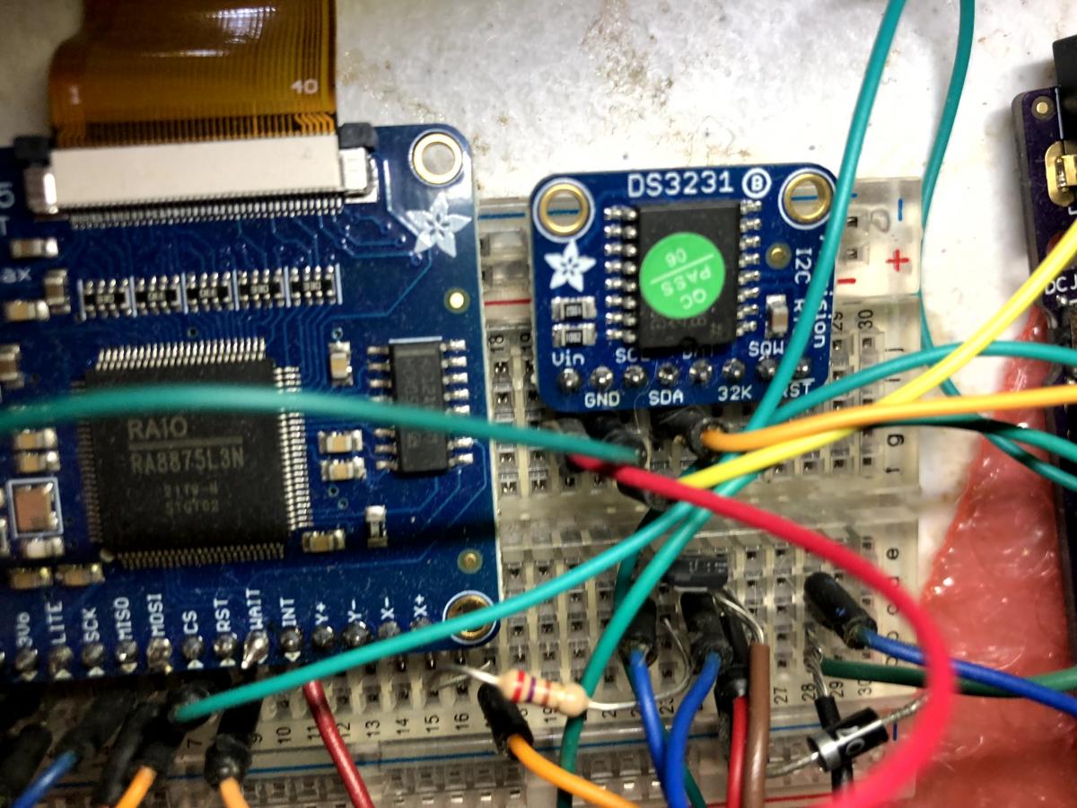
Yeah . . . so the image at right shows the prototype set up as I got the screen working. (This also shows the clock chip, which I'll describe in the next section, mounted on the breadboard.) So, yes, a maze of wires, but the screen was working and I was playing around with all of the drawing tools to see how it looked. I must say, the images and text on the display are crisp and colorful.
Oh, one other thing before I switch over to talking about the clock. I also needed to get the touch interface working. So I just used the tutorial code to initialize the touch sensor, and used the sample code in the main loop of the Metro MX python code to detect touches and display a simple circle where the touch was detected. This is the code for that from the example:
display.touch_init(int_pin)
display.touch_enable(True)
x_scale = 1024 / display.width
y_scale = 1024 / display.height
# Main loop:
while True:
if display.touched():
coords = display.touch_read()
display.fill_circle(int(coords[0]/x_scale), int(coords[1]/y_scale), 4, MAGENTA)
display.txt_color(WHITE, BLACK)
display.txt_set_cursor(display.width // 2 - 220, display.height // 2 - 20)
display.txt_size(2)
display.txt_write("Position (" + str(int(coords[0]/x_scale)) + ", " + str(int(coords[1]/y_scale)) + ")")
As part of the training code, the 'display.width' and 'display.height' values were designed to be read from the driver board, but I never did get those to work quite correctly. It's obviously trying to scale the touch interface to the display's pixel size. I never got this 'sizing' code to work correctly. Instead, I just set up big touch 'button pads' on the screen, and changed the background colors based on touch inputs that were roughly in the right place. That gave me the feedback to understand what coordinate inputs I needed for each control, and I hard coded the tests for those coordinate boxes. That worked sufficiently well that I didn't bother trying to get the scaling function to work.
Initializing the Openweathermap API Calls for Local Weather Data
 Now that I had the screen working, I decided to implement the calls to Openweathermap.org. OpenWeatherMap has free calls to several of their data streams, with limits on the number of calls that can be made over a period of time. These limits have changed (i.e. gotten worse) over time, so I decided to be cautious and only call when I need to. The current limit (as of May 2023) is 1000 calls per day, or about 41 calls to the API per hour, or about one call every 1.4 minutes. But that's for their weather forecast data sets. They have more relaxed restrictions if you just need current weather data, which is what this project needs. For current weather data, the limit is 1 million calls per month, which is about 22 calls per minute.
I don't need updates of the current conditions at anywhere near that frequency. In fact, I decided to be conservative, since I don't know what the future holds for this API, and will only query it about once every five minutes. So I built the CircuitPython code with two timing loops. An outer loop that queries the weather once every five minutes and updates the status of the lighthouse light and sounds, and an inner loop that checks for screen touches and that updates the onscreen clock. The inner loop runs on about tenth of a second timing. I didn't need exact timing on these loops since I'm going to be pulling current time from the RTC chip.
The details of the OpenWeatherMap current weather API is described here on their API documentation page.
To start with, I just needed to create an OpenWeatherMap account, and acquire an API ID. Any calls placed to the API must include the API ID so your usage can be tracked. Initially, I tried to feed the query the name of my state and city to get back current weather data, but that proved a bit too inexact. It also didn't always respond with data that seemed correct for my location. This was the original API call format attempt:
https://api.openweathermap.org/data/2.5/weather?q={city name},{country code}&appid={API key}
I stored the city name, country code, and API key in my secrets.py file on the Metro M4. Pulling in the secrets data used this code:
try: from secrets import secretsexcept ImportError: print("Missing secrets.py file") raise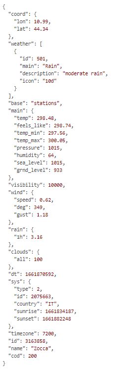 I replaced the city/state data in my secrets file with my latitude and longitude numbers, just pulled from Google map. Calling the API using the browser address bar, I got a sample of data in JSON format, something like this (at right):
response = wifi.get(DATA_SOURCE).json()- weather - description
- main - temp
- main - pressure
- main - humidity
- visibility
- wind - speed
- sys - sunset
- timezone
Attaching the Realtime Clock Board to the Metro MX
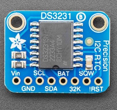 I looked at the weather data as a possible source for current time information, but the source data only gets updated occasionally (around every five minutes), so it wouldn't allow me to keep an onscreen clock running, at least not accurately. For that, I needed a real-time clock chip. So I picked the DS3231 board and chip, which is a temperature-adjusted crystal clock chip with an I2C interface.
Again, it was just a matter of soldering on the header, and then I connected this board on a breadboard to outputs on the Metro M4. This has a very low power draw, so running this and the screen from the Metro M4's pass through power wasn't really an issue during prototyping. Actually, I didn't really have an issue with that until I finally got to the issue of powering the motor and lights on the lighthouse itself, which would have overtaxed the Metro board's power output capabiliites . . . but I'll get to that in my next update.
These were the pin connections:
- Vin to 5VDC from the Metro board
- GND to GND
- SDK (I2C data line)
- SCK (I2C clock line)
Once it was wired and connected to the microcontroller, I downloaded the Adafruit library for this board, and added a few lines of code to add time keeping capabilities to my lighthouse. Actually, I verified that I had three libraries installed to support this:
- adafruit_ds3231.mpy
- adafruit_bus_device
- adafruit_register
So to set up the board in python, I added these lines:
import board
import adafruit_bus_device
import adafruit_ds3231
i2c = board.I2C()
import adafruit_ds3231
ds3231 = adafruit_ds3231.DS3231(i2c)
ds3231.datetime = time.struct_time((2023, 5, 20, 15, 35, 0, 6, 1, -1))
The last line there was just to set the current date and time on the RTC chip the first time. I deleted that line after the first time, and the battery on the DS3231 retained the current date and time. To pull the current time, I just called:
current = ds3231.datetime
Which brought the current date and time into a Python time structure. From this, I could pull the day of the month as: current_date = current.tm_mday, and so on.
All right, from this point, I've got the screen working. I've got the current weather and sunset time. I've got the accurate local date and time. Up next, building out the onscreen interface, and actually wiring the Metro M4 controller to the lighthouse motor and lights. I'll talk in more detail then about the overall code. But I'll also share my main code file now, because I promised that in the last update.

