Lighthouse update: Soundboards and MX Board Setup
Primary tabs
So far, I've described the overall idea for the smart weather lighthouse, and what the various systems of the build will be, but let me lay out the stages to this build . . . since it is a bit complicated. These are the steps I went through to pull it together:
- Configuring the sound boards, speakers and audio sample files
- Setting up the MX board with Circuitpython and activating wifi and basic code
- Attaching the touchscreen driver board and touchscreen to the MX board
- Initializing the Openweathermap API calls for local weather data
- Attaching the realtime clock board to the MX
- Building the basic touchscreen user interface
- Wiring the lighthouse lights and motor to the MX board
- Triggering sound effects with the MX Board
- Building the wooden lighthouse base
- Installing the electronics into the base
I have to say that I couldn't have pulled together all of the electonics and coding without the excellent support of the Adafruit projects and learning pages.
Soundboards, Speakers, and Audio Samples
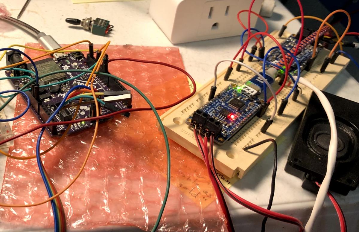
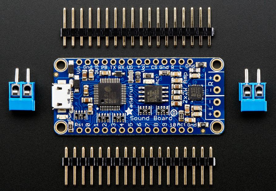 Since the sound of a lighthouse on a Youtube video, played while the Lego lighthouse was running in a darkened room, triggered the desire to build this project, I decided to put together the sounds and sound system first. I opted for the larger 16MB size (it also comes in 2MB) of the Adafruit Sound Board FX product. I ordered two, because I wanted two independent sounds to be playable and triggerable at any time. These boards can generate stereo output, but only from one sound file at a time. The benefit of this particular product is that it doesn't logically link or need to be interfaced to the microcontroller. It houses the sound files, has independent power, and takes a simple voltage LOW signal to trigger a sound file to play. This is important, since it takes the processing load off of the arduino-compatable MX board for audio.
It comes in two flavors (besides the memory size). One has a miniRCA jack to allow audio out /a headphone to be plugged in. But I wanted to drive speakers directly, so I opted for the board with the built-in audio amp, and speaker terminals. (The blue parts to the left and right of the main board in the photo above.)
 So, first things first, I soldered the headers and the speaker terminals in place. Operating it is simple. The speaker terminals go at the right end of the board as shown above.
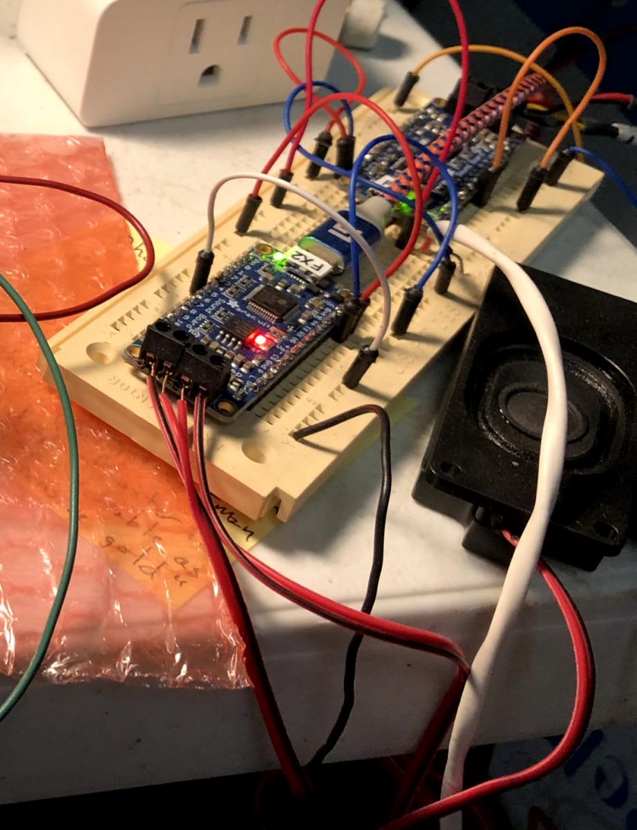
After assembly, I just plugged the board into a breadboard, provided power to the Vin pin, and grounded the GND pin. And then I wired two pairs of speakers to the two FX boards. I labeled the boards 'FX1' and 'FX2'. FX1 will be used for background sounds, and I wired that one to the smaller Adafruit mini speakers.
The FX2 board is for sound effects . . . particularly the foghorn sound. This will be triggered occasionally as the weather situation changes. FX2 is connected to a pair of larger 8 ohm Panasonic speakers I had on hand. These provide a nice heavy base for the foghorn sound effect.
 Triggering the sound effects on these boards uses an elegant and simple approach. The pins number 0 through 10 are trigger inputs. Whenever a pin goes logic low (0V) that sound effect will be played. There are some enhancements to this, though, based on the file names of the sound files.
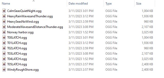
At the opposite end of these FX boards from the speaker terminals is a USB micro port. If you plug the board into a USB cable and connect it to a PC, the Sound Board FX will show up as a drive on your computer. If one simply drags and drops audio files to the drive folder, they're saved to the FX board. The board can handle either a .wav file or an .ogg file for compressed audio. Using a .ogg file, one can play up to 15 minutes of high quality stereo audio out of one of these 16MB boards. I didn't need nearly that much space. The above folder snapshot shows my working folder for audio files for the 'background' or FX1 board.
I captured the audio using Audacity from several Youtube videos. I briefly considered buying some royalty-free samples from Pond5, but opted to just capture Youtube audio samples because I'm not selling this or trying to make money off of this project. It's just for me. So that's why I'm not providing these audio files as downloads here. You can take your own samples, if you'd like.
The important aspect of this is that the file names determine how the FX board plays them. Of the sample files shown, I only loaded those with names starting 'T0' onto the board. The T0 name indicates which trigger will play that sound. So 'T00.ogg' will play if the 0 pin is sent low. These files can also have modified behavior if you add text to the name. 'T00LATCH' for example will play the audio file continuously until another pin is triggered, or this pin is triggered again to turn off the sound. There are ways to play a set of sounds in sequence ('T00NEXT0', 'TOONEXT1', etc.) or at random ('TOORAND0','TOORAND1', etc.) and a couple other options, but I only used LATCH and the basic file play for this project. Simply Triggering a file named 'T00.ogg' will start and play the file one complete time through. The background noises shown above are all set to LATCH and play continously in the background. I opted for six different sound files, based on weather conditions, ranging from calm waves, to windy harbor sounds, to a raging thunderstorm.
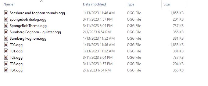 The F2 board's sounds are what I've called 'overlays'. This is where I'm storing the foghorn sounds, as well as a couple other fun sound effects.
To test this setup, I loaded the files and then manually triggered them by using a patch wire to ground each of the trigger pins . . . testing each sound effect one by one.
I'll note that the onboard audio amp is not terribly powerful. It's intended to be powered by batteries for cosplay rigs and other portable scenarios, although I'll be powering this with a 5V wall wart. But it is perfectly adequate for the lighthouse sounds. The little 4 ohm mini speakers are not loud, but they suffice for a background sound effect. The larger speakers, even run by this simple sound effects board can be quite loud. The board itself can handle power input from 3 to 5.5 VDC, but the more voltage supplied the louder the sound. The boards are output limited to 6dB gain so people don't blow out their speakers.
Setting up the Metro MX board with Circuitpython
 Adafruit has a whole line of Arduino-compatible boards called Metro boards. I picked the Metro M4 Airlift Lite, which may be slightly overkill for this project, but when I started the prototyping, I wasn't sure how far I was going to push this. I like it because, with 2MB of Flash, it can host a large circuitpython program. It has built-in USB. It has an Airlift wifi chip onboard. Lots of digital and analog input and output pins, and the Cortex M4 runs at 120MHz, so it's FAST when it comes to Arduino type boards. This last item turned out to be critical for the touch-screen interface.
Oh, and the variety of serial comms options turned out to be important as well. I'm using I2C for the clock interface, and SPI for the screen interface.
I'll not go into a ton of detail on setting up the Metro M4, other than to say I used the project page for the Lunar matrix calendar display (which I built using this board in the past) instructions to get the basic Circuitpython load onto the board and the simple IO and Wifi setup configured. Using the materials from the Adafruit instructions, I'm putting all the critical config details in a separate secrets.py file. This includes the login for my home wifi, and details about my latitude and longitude for weather details. I'm obviously not sharing the secrets file, but I will post the full program file I have running on the Metro M4 in my next project update.
I can mention that I ended up with over 1000 lines of code for this project (but I tend to be verbose when it comes to commenting code) and I'm not going for code efficiency as much as just getting it working. I'm sure a real Python developer would do it more elegantly than I have.
 So, basics. I plugged in a USB C cable between the Metro M4 and my PC, and loaded the Circuitpython image to flash. Once that was done, the board showed up as a virtual drive on my computer. At that point, I used the Mu editor to edit Python code in the code.py file stored on that drive. (I also uploaded by secrets.py file, the support libraries I needed for the various modules and packages, and a few other support files.)
As I worked on this project, I moved back and forth between powering the board with the USB cable from the PC, and supplying Vin (5VDC) and GND directly. That's where I had this after a couple days of effort. The sound files working on the FX boards, the MetroM4 powered with Circuitpython loaded and able to reach the internet through my home network over wifi. Up next, connecting the screen and the screen driver board, and the I2C clock board. But this is already too long, so I'll save those for next time.

